Categories
Hardware Music Projects

PicoWaveTracker: A MIDI Step Sequencer That Writes the Notes For You

PicoWaveTracker is a MIDI step sequencer built around a Raspberry Pi Pico, an OLED screen, a rotary encoder, and an 8×8 NeoPixel matrix standing in for the usual grid of step buttons. Turn the encoder to move between steps, click to edit a note, hold to start or stop playback — the kind of tracker interface I’ve always liked, minus the wall of physical buttons.

What makes it more than “yet another step sequencer” is that half the tracks don’t have to be programmed by hand. Alongside the regular manual track, there’s a set of generative strategies you can hand a track over to instead — Euclidean rhythms, L-systems, cellular automata, Markov chains, arpeggios, call-and-response, drones, even a “lucky” random strategy. Each one turns a track into a little algorithm instead of a fixed pattern, and you can run several tracks at once with different strategies and step counts, which gets you polyrhythms almost for free.

A lot of the later work went into making the generated parts actually sound musical instead of just correct: scale and root-note awareness so the algorithms stay in key, a mutation setting with adjustable intensity so patterns drift instead of jumping randomly, and chord-note support so “harmony” means something beyond a single melodic line. There’s also a dedicated drone strategy for when you just want a track to hang in the background.

The hardware side had its own fights: the NeoPixel matrix draws more current than the Pico can supply on its own, so it needs a separate 5V line, with real warnings about not doing this the lazy way and frying a USB port. I also hit a deadlock where the watchdog would restart the whole device if a MIDI lock got acquired twice in a row — the kind of bug that’s obvious in hindsight and infuriating in the moment.

To make this build extra fun, I repurposed a kids’ toy briefcase and made it a bit punk.

Full wiring diagrams, power options (including a portable LiPo setup), and the code for all the generative strategies are in the PicoWaveTracker repository.

Categories
Hardware Music Projects

NoiceSynth: A Grid-Based Modular Synth You Can Fit in a Tin

Modular synths are great fun, but they usually mean a rack, a pile of patch cables, and a wallet that’s a lot lighter than it used to be. NoiceSynth is my attempt at getting that same “patch it together yourself” feeling into something that fits in a tin box and runs on a single Raspberry Pi Pico.

Instead of a fixed synth architecture, you get a 12×12 grid. You place modules on it — oscillators, filters, envelopes, and a handful of others — and wire them together however you like. Want a patch that leans into DX7-style FM synthesis? Build it. Want a slow, drifting drone instead? Same grid, different wiring. The “instrument” is whatever you’ve patched together.

Under the hood, it’s an RP2040 doing the DSP work, streaming audio out over I2S for clean output. Controls are kept minimal on purpose: a rotary encoder for navigation, a potentiometer for volume, and a 128×64 OLED for visual feedback on whatever you’re doing to the patch. A 3.5mm TRS-A MIDI input lets it take notes from an external keyboard or sequencer, and the whole thing is designed to run off a LiPo cell and a booster board — small and portable enough to actually carry around.

A fair amount of the actual build time went into things you’d never notice from the outside: getting I2S audio streaming without glitches meant adding proper buffering, and once that was stable, I moved the synthesis math over to fixed-point to keep the Pico’s core from choking under a full patch. Patches themselves get saved to EEPROM, so nothing’s lost when you power it off.

There’s also a desktop simulator included, which turned out to be more useful than I expected — it lets you design and audition a patch at your desk before ever touching the hardware, and you can transfer patches back and forth between the two. It ships with eight demo patches plus a few built-in presets that mimic the DX7.

Full build instructions, wiring diagrams, and the source are all in the NoiceSynth repository.

Categories
Hardware Music Projects

StupidSynth: Turning a Decade-Old Raspberry Pi Into an Instant-On Synth

Every Raspberry Pi I own boots into a whole Linux distro before it does anything, which felt like overkill for the one thing I actually wanted: something that makes a sound the moment it’s powered on. StupidSynth throws out the OS entirely — it runs bare-metal on an original Raspberry Pi 1 (or Zero), boots straight into the synth code in one to two seconds, and starts playing.

Once it boots there’s nothing to configure and nothing to press. It just loops a randomly generated melody as a single-voice sawtooth wave out the 3.5mm jack, while the composite video output draws a bare red bar that pulses with the amplitude. No filesystem, no drivers beyond what the synth itself needs, no input handling at all.

The actual interesting part is everything that has to happen before “Hello, World” even makes sense on hardware like this. There’s no libc, no OS, so kernel.c has to be the entire universe — audio generation, video timing, and a boot stub in assembly that hands control over from the Pi’s own firmware in the first place, all built with a bare gcc-arm-none-eabi cross-compiler and linked against a custom linker script. Getting the deploy loop fast enough to be worth iterating on mattered more here than usual, so there’s a Distrobox-based dev container and a script that finds the SD card, copies the built kernel and firmware onto it, and unmounts it — no manual dd-ing required.

This one’s deliberately small and dumb, hence the name, and it only runs on the original BCM2835-based boards (Pi 1, Zero, Zero W), not anything newer. Full source, the deploy scripts, and manual setup instructions are in the StupidSynth repository.

Categories
Hardware Projects

washing-machine-notify: Knowing When the Laundry’s Done Without Modding it

I got tired of walking to the utility room just to check if the washer or dryer had finished, so I built a little ESP32 gadget — with an AI coding assistant doing most of the actual typing — that watches both machines and pings my phone the moment a cycle starts or ends.

The trick is what it actually senses. Rather than tapping into the machines electrically or measuring vibration, it just watches light — a BH1750 sensor taped over each machine’s own “running” indicator LED. If the light’s on, the machine’s running; when it goes off, the cycle’s done. It’s about as non-invasive as monitoring gets, and it works on basically anything with a status light, not just my specific washer and dryer.

I actually started with vibration sensing instead, measuring a window of motion to decide if a machine was active, but it ended up simpler and more reliable to just watch the light. Getting the timing logic right so a brief flicker doesn’t count as a full cycle took a few passes, and it all runs non-blocking off millis() so the WiFi connection and the display stay responsive.

Notifications go out over a self-hosted ntfy.sh topic rather than a proprietary app or cloud service, and there’s a small OLED on the device itself for an at-a-glance status if my phone’s not around.

It’s since been retired, though — I replaced the whole setup with an IKEA smart plug and Home Assistant, which tracks power draw instead of light and needed zero custom firmware. Still, wiring, parts list, and the full sketch are in the washing-machine-notify repository, in case the light-sensing approach is useful for a machine that doesn’t play nicely with a smart plug.

Categories
Hardware Projects

thermoprint-homework: Turning a Receipt Printer Into an Endless Worksheet Machine

I had a cheap thermal receipt printer doing nothing, and a son who needed to practice a few skills for school. thermoprint-homework — built almost entirely with an AI coding assistant — turns the two into an endless supply of one-page worksheets: run the server, hit print, get a fresh sheet.

What started as a plain TUI printing basic math problems quickly turned into a small library of “jobs”: unit conversion, decimal division, a division-based cipher, mazes with adjustable difficulty, word search puzzles, chess puzzles pulled from randomly generated positions via a chess library, even a random joke thrown in for good measure. Each one is its own self-contained job that gets queued and printed.

The newest addition isn’t practice material at all — it reads my son’s schedule straight from a Google Calendar via its private iCal feed and prints out today’s tasks, so he’s got a physical slip telling him which chores are due and whether he’s got an activity to head out to, instead of having to ask.

It’s built on python-escpos, so anything ESC/POS-compatible should work, not just the specific printer I’m using. Full job list, config, and setup instructions are in the thermoprint-homework repository.

Categories
Awesome Hardware Linux

Orange Pi Zero running in QEMU

I needed a way to run an Orange Pi Zero SD-Card image of Armbian as a virtual machine. And this is actually possible with QEMU!

This is the command I used:

qemu-system-arm \
-M orangepi-pc -m 1024 -cpu cortex-a7 -dtb boot/dtb/sun8i-h3-orangepi-pc.dtb \
-kernel boot/vmlinuz-5.4.45-sunxi -initrd boot/initrd.img-5.4.45-sunxi \
-append 'earlyprintk loglevel=8 earlycon=uart8250,mmio32,0x1c28000,115200n8 console=ttyS0 root=/dev/mmcblk0p1' \
-nographic -serial stdio -monitor none \
-drive file=Armbian_20.05.3_Orangepizero_buster_current_5.4.45.img,format=raw,if=none,id=d1 \
-device sd-card,drive=d1 \
-nic user,model=allwinner-sun8i-emac,hostfwd=tcp::50022-:22

Original source: https://forum.armbian.com/topic/7547-run-armbian-into-qemu/?tab=comments#comment-86797

You need to get the contents of the /boot directory from the SD Card image so that you can start booting it. I just used scp to copy it from a running Orange Pi Zero to my main machine. The command above doesn’t actually run an Orange Pi Zero board, it runs an Orange Pi PC, though this is almost the same thing. At least the CPU is the same (note: Allwinner H2+ and H3 are binary compatible). But it has more memory!

Why run Armbian in QEMU?

I wanted to compile an application written in Rust. The problem was that installing it the official way through rustup (or more precisely rustup-init) resulted in an error:

info: installing component 'cargo'
info: Defaulting to 139.4 MiB unpack ram
thread 'main' panicked at 'RUSTUP_UNPACK_RAM must be larger than 220000000', src/dist/component/package.rs:200:13
note: run with `RUST_BACKTRACE=1` environment variable to display a backtrace
thread 'main' panicked at 'No process instance', src/currentprocess.rs:126:17

The newer versions of rust required more memory than the Orange Pi Zero had! Mine had 256 MB (since I thought I’d take this as a challenge instead of going with the 512 MB version). Rustup needed at least 220 MB on its own.

Alternatively I could get some cross-compilation toolchain. But that seemed even harder; I couldn’t find anything usable.

Categories
Hardware

Serial Connection to Orange Pi 4

I thought I’d use my trusty CP2102 USB-UART adapter. But as it turns out, it only works up to 1 Mbps, while the Orange Pi 4 is running at 1500000 bauds. Oops.

My other attempt was to try the Raspberry Pi‘s serial port, but that also didn’t work. The data coming in was also just a random garbage.

I tried using a random Arduino‘s on board serial module CH340 (while having Reset hooked up to GND so that it bypasses the Atmel chip) but that for some reason didn’t produce any data on the high baud rate. Even though based on the specification of the chip the baud rate should be supported.

My next attempt was with an ESP32 dev board, hooking it up similarly to an Arduino. No luck, turns out there is again the CP2102 chip. There was some output from the Orange Pi 4, but again it was garbage since it can’t keep up at this speed.

Finally I found a lonely DAPlink module that is specifically designed for ARM programming. Among other things it has a UART with 3.3V TTL levels. And bingo, this one was fast enough to finally read the Orange Pi 4’s debug UART port.

Categories
Awesome Linux Open source PinePhone Projects

Mouse in a Pipe

Have you ever wanted to control your notebook directly from your desktop? How about controlling your phone? Wouldn’t it be better to type that chat message using a real keyboard? I wanted the same thing, so I wrote an app for that!

More precisely I created a tool that enables you to redirect mouse and keyboard events from one device to another. It’s like you reconnected your mouse and keyboard, but without the physical effort! All of this happens on a very low level (through the kernel) so this works seamlessly with any application you want to control. All you need is a Linux OS on both of the devices.

Repository: https://github.com/Dejvino/mouse-piped

One more interesting point is that the input events are pushed through a pipe, which is a generic way of transferring data among processes in Unix-based operating systems. It is up to you how you decide to transfer the data. Though most likely it will happen via SSH. You can easily generate input events on your main computer and then pipe them through SSH to your secondary computer (or a phone) and control it that way. Or you might decide to create a TCP connection and pass the data through that. That’s up to you!

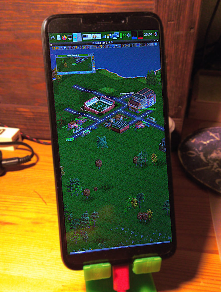
And you know what else is this useful for? That’s right, you can finally play OpenTTD on a PinePhone with the full comfort of a mouse and keyboard!

Categories
Linux Open source PicoPosts PinePhone Projects

Arch Linux ARM Installer for PinePhone

I started building an automated Arch Linux ARM installation and customization set of scripts to be used for the PinePhone. The aim is to make the process easier while still being able to customize every aspect of the OS.

Repository URL: https://github.com/Dejvino/pinephone-arch-install

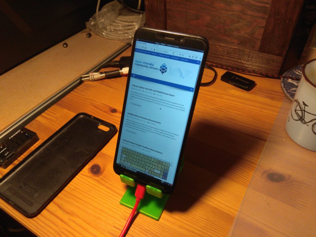
Arch Linux ARM running LXDE, Firefox and Onboard keyboard.

Arch Linux ARM was the best OS for PinePhone I’ve seen so far. It might be due to personal preference, but I just love how you have the full power of Arch on your mobile phone.

And if Arch is not your thing, at least you can learn what are the steps required for bringing a Linux OS into a PinePhone.

Categories
Linux PinePhone

Errors During PinePhone Install

I learned a lot about hardware and operating systems since I received my PinePhone. A lot of times it was during error investigation. With a small chance that this information might get picked up by another PinePhone enthusiast, I’ll post the error messages and my solutions here.

RTL firmware not found

Bluetooth firmware on my Arch Linux ARM was missing, it is a non-free firmware so it is not included by default.

Feb 23 19:21:58 alarm kernel: bluetooth hci0: Direct firmware load for rtl_bt/rtl8723cs_xx_fw.bin failed with error -2
Feb 23 19:21:58 alarm kernel: Bluetooth: hci0: RTL: firmware file rtl_bt/rtl8723cs_xx_fw.bin not found

With this I just went over to my postmarketOS SD Card image and copied the corresponding files from /lib/firmware/rtl_bt/ over SSH

scp lib/firmware/rtl_bt/rtl8723cs_xx_fw.bin root@pinephone_ip_address:/lib/firmware/rtl_bt/
scp lib/firmware/rtl_bt/rtl8723cs_xx_config-pinebook.bin root@pinephone_ip_address:/lib/firmware/rtl_bt/rtl8723cs_xx_config-pinephone.bin # notice the rename

systemd-binfmt Failed

I was getting a lot of binfmt-related errors like the ones in bold below. And if there is one thing you don’t want to see it is a red FAILED log line during boot process.

[...]
Feb 23 19:36:10 alarm systemd[1]: Mounted Temporary Directory (/tmp).
Feb 23 19:36:10 alarm systemd[1]: Started Create list of static device nodes for the current kernel.
Feb 23 19:36:10 alarm systemd[1]: systemd-binfmt.service: Main process exited, code=exited, status=1/FAILURE
Feb 23 19:36:10 alarm systemd[1]: systemd-binfmt.service: Failed with result 'exit-code'.
Feb 23 19:36:10 alarm systemd[1]: Failed to start Set Up Additional Binary Formats.
Feb 23 19:36:10 alarm systemd[1]: Started Load Kernel Modules.
[...]
Feb 23 19:36:10 alarm systemd-binfmt[267]: Failed to add binary format: No such file or directory
[...]
Feb 23 19:36:13 alarm systemd[1]: Starting Load/Save RF Kill Switch Status…
Feb 23 19:36:13 alarm systemd-binfmt[385]: Failed to add binary format: No such file or directory
Feb 23 19:36:13 alarm systemd[1]: Condition check resulted in Create System Users being skipped.
Feb 23 19:36:13 alarm systemd[1]: systemd-binfmt.service: Main process exited, code=exited, status=1/FAILURE
Feb 23 19:36:13 alarm systemd[1]: systemd-binfmt.service: Failed with result 'exit-code'.
Feb 23 19:36:13 alarm systemd[1]: Failed to start Set Up Additional Binary Formats.
Feb 23 19:36:13 alarm systemd[1]: Started Load/Save RF Kill Switch Status.
[...]

So I went to investigate the service’s config files, seeing the “Failed to add binary format: No such file or directory” error. There are several directories that binfmt is looking for its config files. As it turns out all of them were empty apart from one. I found out that after installing mono it registered itself with binfmt. Not sure why, but I certainly don’t need it, so the solution is simple.

rm /usr/lib/binfmt.d/mono.conf 

Done!

Broken Battery In ACPI

Multiple components make use of the ACPI and all of them report a dead battery. E.g. battery applet or laptop-mode service:

Feb 23 19:22:05 alarm laptop-mode[1653]: Failed to re-set power saving mode for wireless card
Feb 23 19:22:05 alarm laptop-mode[1700]: WARNING: Battery does not report a capacity. Minimum battery
Feb 23 19:22:05 alarm laptop-mode[1701]: charge checking does not work without a design capacity.
Feb 23 19:22:05 alarm laptop-mode[1702]: WARNING: Battery does not report a design capacity. Auto hibernation
Feb 23 19:22:05 alarm laptop-mode[1703]: does not work without a design capacity.
Feb 23 19:22:05 alarm laptop-mode[1704]: You seem to have a broken battery
Feb 23 19:22:05 alarm laptop-mode[1705]: Cannot determine design_capacity_warning
Feb 23 19:22:05 alarm laptop-mode[1706]: Disabling hibernation
Feb 23 19:22:05 alarm laptop-mode[1707]: Failed to determine battery charge. Battery charge units are not in
Feb 23 19:22:05 alarm laptop-mode[1708]: mWh, uWh, mAh or uAh.
Feb 23 19:22:05 alarm laptop-mode[1711]: enabled, active

This is not the case since the battery is actually fine, it just doesn’t work with ACPI:

# cat /sys/class/power_supply/axp20x-battery/uevent 
POWER_SUPPLY_NAME=axp20x-battery
POWER_SUPPLY_PRESENT=1
POWER_SUPPLY_ONLINE=1
POWER_SUPPLY_STATUS=Discharging
POWER_SUPPLY_VOLTAGE_NOW=4112000
POWER_SUPPLY_CURRENT_NOW=429000
POWER_SUPPLY_CONSTANT_CHARGE_CURRENT=1200000
POWER_SUPPLY_CONSTANT_CHARGE_CURRENT_MAX=1200000
POWER_SUPPLY_HEALTH=Good
POWER_SUPPLY_VOLTAGE_MAX_DESIGN=4200000
POWER_SUPPLY_VOLTAGE_MIN_DESIGN=2900000
POWER_SUPPLY_CAPACITY=95

Seems the kernel I’m using doesn’t have it enabled, as you can see here:

#  ls -l /usr/lib/modules/$(uname -r)/kernel/drivers/acpi
ls: cannot access '/usr/lib/modules/5.6.0-rc1-00239-geb93b104bbccb/kernel/drivers/acpi': No such file or directory